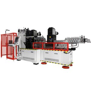
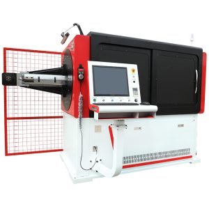
One-stop Bending Solutions For Wires, Tubes And Pipes
One-stop Bending Solutions For Wires, Tubes And Pipes
As specialized equipment in the spring machinery field, automatic wire bending machines‘ core function is to precisely bend various types of wire. As market demands for product precision and quality continue to rise, the proper operation of automatic wire bending machines not only directly impacts production efficiency and the yield rate of finished products, but also has a significant impact on the operator’s personal safety and the lifespan of the equipment. The following detailed analysis of the key operating considerations for automatic wire bending machines provides comprehensive guidance for practical production operations.
Ⅰ. Before Starting the Automatic Wire Bending Machine
1. Thoroughly Check the Tightness of the Tool Fixing Screws
The tooling of an automatic wire bending machine is the core component that ensures bending accuracy. It primarily consists of six components: the wire feed wheel, the conductor plate, the cutting blade, the angle plate, the angle core, and the angle blade. Any looseness in any of these components can cause the wire to deviate, the bending angle to deviate, or the cutting to be uneven. Before operation, use a wrench of the appropriate size (e.g., Allen key, open-end wrench) to check the screws securing each tool individually:
• Feed wheel screws: Ensure that both screws are evenly tightened to avoid overtightening on one side, which can cause the feed wheel to stall and affect wire feeding speed and stability.
• Cutting knife and bend cutter screws: Focus on inspecting the screws securing the blades. Looseness can cause burrs on the wire during cutting or tool shifting during bending, resulting in angular errors.
• Wire guide and bend plate/core screws: The wire guide must be aligned with the centerline of the feed wheel. Loose screws can easily cause wire to shift during feeding. The bend plate and core rely on screws for coaxiality. Looseness can directly cause deviations in the bend radius, affecting product consistency.
After inspection, perform a test push test: Gently push each tool manually to confirm there is no shaking or displacement before proceeding to the next step.
2. Adjusting the Wire Feed Roller Clamping Screws After Long-Term Downtime
If the automatic wire bending machine is unused for an extended period (over 72 hours) due to production schedule adjustments, holidays, or other reasons, the wire feed roll clamping screws—three 19mm hexagonal screws located above the wire feed box—should be loosened promptly. Prolonged clamping can cause deformation of the wire feed roll surface due to uneven force. Furthermore, the internal bearings may lose lubrication due to prolonged fixed force, shortening their service life. When loosening, please note the following:
• Force Control: Use a 19mm socket wrench to loosen the screws slowly. Avoid excessive force that could cause the screws to strip.
• Loosen to a desired degree: The wire feed roll should rotate freely without noticeable pressure. Complete disassembly is not necessary.
• Restarting the machine: Before restarting, adjust the clamping force based on the wire diameter being processed. For thicker wires (e.g., ≥5mm), tighten appropriately to prevent slippage during feeding. For thinner wires (e.g., ≤1mm), reduce the pressure to prevent deformation.
3. Pre-Startup Inspection of the Automatic Wire Bending Machine
Pre-startup inspection is a critical step in preventing batch scrapping and is performed in two steps:
• Step 1: Handwheel Simulation Run Test. By turning the handwheel on the side of the machine, the mechanical structure slowly operates according to the preset program. Observe the smooth operation of each component (e.g., smooth transitions during wire feeding, bending, and cutting), and any jamming or unusual noises. Verify that the bending angle and wire feeding length are consistent with the programmed values. If any deviation is detected, immediately pause and investigate any issues with the program parameters or mechanical structure. Do not restart the machine immediately.
• Step 2: Verify that the tool matches the product and wire diameter. Different products (such as springs, wire supports, and special-shaped bent parts) require different tool specifications (e.g., bevel radius and cutter blade angle). Furthermore, the wire diameter (e.g., 0.8mm, 3mm, 6mm) must be adapted to the tool. For example, if the wire diameter exceeds the tool’s maximum adaptability, the cutter blade may break or the wire feed reel may become stuck. If the wire diameter is too thin, excessive tool clearance may result in insufficient bending accuracy. Before operation, verify that the installed tool model and wire diameter match the order’s specifications against the product specifications included in the production order. Only after confirmation can the machine be started up.
4. Unauthorized modification of equipment parameters is strictly prohibited.
Equipment parameters (such as wire feed speed, bending delay time, cutting stroke, and pressure value) are determined by technicians through repeated adjustments based on product characteristics and wire material (e.g., carbon steel, stainless steel, or copper wire). They directly impact processing accuracy and equipment safety. Unauthorized parameter modification can cause multiple problems:
• Excessive wire feed speed: This may result in excessive wire feeding, leading to wire accumulation during bending. Excessively slow speeds reduce production efficiency and may cause localized overheating due to prolonged wire dwell time.
• Inappropriate bending delay time: Too short a delay can cause conflict between bending and wire feeding, resulting in mechanical shock. Too long a delay can cause wire loosening and affect angle accuracy.
• Pressure deviation: Excessive pressure can crush the wire or damage the tool, while too low a pressure can prevent bending or cutting.
If parameter adjustments are required due to product changes, they must be performed by professionally trained technicians and verified through a small-batch trial run. Only after the parameters are confirmed to be correct can mass production begin.

II. Automatic Wire Bending Machine Operation
1. It is strictly forbidden to approach the working area of the automatic wire bending machine with your hands.
When the automatic wire bending machine is in operation, components such as the wire feed wheel, cutting blade, and beveling blade are rotating at high speed or in reciprocating motion. This creates a high risk of mechanical injuries (such as pinching, cutting, and entanglement) in the working area. Strictly adhere to the following during operation:
• Hand Distance Requirements: Keep your hands 30cm away from the working area (defined by the tool’s trajectory). Do not touch the feeding wire, the rotating wire feed wheel, or the end of the wire to be cut.
• Abnormal Handling Procedures: If you notice any abnormalities such as wire deviation or jamming, immediately press the emergency stop button. After the machine comes to a complete stop, use specialized tools (such as tweezers or hooks) to clean or adjust the machine. Do not directly intervene with your hands while the machine is operating.
• Maintaining Vision: Maintain a clear view of the working area during operation. Do not operate the machine while distracted, such as looking down at an order or making a phone call.
2. Cutting must be performed using the cutter button; manual cutting is prohibited.
The cutting function of the device is designed as “electric quick cut” and must be completed via the operation panel. Manual cutting using the handwheel is prohibited for the following reasons:
• Risks of manual cutting: The cutter blade moves slowly and applies uneven force when manually cranking, which can easily cause burrs and deformation on the cut surface. Insufficient manual force can even cause the cutter blade to become stuck in the wire, causing damage to the blade or equipment stalling.
• Correct operation steps: ① Select the “Manual” button on the operation panel to ensure the device is in manual operation mode. ② After confirming that the cutter blade is in place, click the “Cut” button. The cutter blade will then quickly complete the cut at the preset speed, ensuring a smooth, burr-free cut surface. ③ After cutting, check that the cutter blade has automatically reset. If it has not, investigate for material jamming or parameter abnormalities.
3. Do not open the safety door while the automatic wire bending machine is operating.
The safety door is a core safety feature of the machine. Its function is to form a physical barrier, preventing personnel from accidentally entering the work area and preventing injuries from flying iron and wire debris generated during processing. When operating the machine, please note the following:
• Safety door status check: Before starting the machine, ensure that the safety door is securely closed and the safety door latch is locked (some machines are equipped with a safety door sensor; if it is not closed, the machine will not start).
• Prohibited operation during operation: During machine operation, regardless of any abnormalities, do not open the safety door. If an abnormality requires attention, press the emergency stop button first and wait until the machine comes to a complete stop before opening the safety door.
• Safety door maintenance: Regularly check the safety door lock, hinges, and seal for signs of wear and tear. If the safety door is damaged or cannot be locked, immediately shut down the machine and report the problem. Do not operate the machine with a faulty door.
4. Prohibit simultaneous operation by two or more people.
The operating procedures of an automatic wire bending machine are continuous and unique. Simultaneous operation by multiple people can easily lead to command confusion and conflicting actions, increasing the risk of accidents. For example, if one person adjusts the wire feed reel while another accidentally presses the start button; or if one person removes scrap metal while another presses the cut button, both can result in injury. Therefore, the “one person, one machine” operating principle must be strictly adhered to:
• Clear operating authority: Each machine must be operated by a designated person. Operators must be familiar with the machine’s full operating procedures and emergency procedures. Non-designated personnel are prohibited from touching the operating panel or machine switches.
• Collaboration standards: If two people are required to work together (e.g., changing wire or moving finished products), the machine must be shut down and powered off. During collaboration, clear division of labor must be maintained to avoid simultaneous contact with machine operating components.
5. Do not touch “touch points” while the equipment is operating.
“Touch points” on equipment primarily refer to key components such as high-voltage terminals, motor shafts, transmission gears, and chains. These components present risks of electric shock and entrapment during operation:
• Electrical touch points: These include the terminal blocks inside the equipment’s distribution box and the line connectors below the operator panel. High voltage is present during operation, and touching them could result in electric shock.
• Mechanical touch points: These include motor shafts, transmission gears, and chains. These components rotate at high speeds, and touching them could entrap fingers or clothing, causing serious pinching or lacerations.
Touch points on equipment are typically marked with prominent warning signs (such as “Do Not Touch” and “High Voltage Danger”). Operators must remember the location of these signs and avoid approaching or touching them during operation. Routine maintenance should also be performed after power is turned off.
6. Strictly adhere to “No Standing Areas” regulations.
A “No Standing Area” on equipment refers to a specific area (usually marked by yellow warning lines on the sides or rear of the equipment) that presents a safety risk during operation due to factors such as component movement and debris splashing. Reasons for prohibiting standing include:
• Component Movement Risk: Some equipment’s corner mechanisms extend to the sides during operation, and standing in the No Standing Area could result in collisions with moving components.
• Debris Splash Risk: Iron and wire debris generated during processing could fly toward the No Standing Area, causing eye and skin injuries.
• Emergency Operation Space: The No Standing Area also houses the operating area for the equipment’s emergency stop button and emergency switch. Standing there could hinder emergency operations.
Operators must be familiar with the No Standing Area for each piece of equipment and must stand in the designated safe operating area during operation (usually in front of the equipment, clearly separated from the No Standing Area). Temporary rest or placement of objects in the No Standing Area is prohibited.
If you have any questions or needs about automatic wire bending machines, please feel free to contact us.
Previous Articles:
The core advantages of CNC wire bending machine
How to choose a fully automatic pipe bending machine suitable for shipbuilding?
Our equipment has CE, ISO quality inspection certificate, so the quality is guaranteed to be cost-effective. According to different processing requirements, machines can be customized to fit for your usage, to provide customized services. In the processing period, we strictly control the production process, to ensure the quality of clearance, standardize the process, strict implementation.
